|
||||||||||
| Features |
|---|
|

| System specifications | |
|---|---|
| Number of output channels supported | 1-16 |
| User interface | Controller, rack mounted “Orion” (touch screen or Ethernet access) |
| Chassis earth ground connection(s) | Dual lug female 1/4” x 5/8” (2) bolts provided in hardware kit |
| Alarm connections |
Multiple; see Quick Start Guide. (4) connectors provided6 |
| Redundancy (per channel) | 1+1 capable, redundancy plates included with 16-channel shelf |
| Electrical - boost | |
|---|---|
| Input connections | Dual lug studs 1/4”-20 x 5/8” (nuts provided / pre-installed) |
|
Input voltage range1 (VDC) |
-38 to -58 |
|
Input current per feed, max2 (A) |
220 |
| DC input breaker sizing (per feed), min3 (A) | Channel-dependent. See Quick Start Guide |
| Output connections | Dual lug studs 1/4”-20 x 5/8” (nuts provided / pre-installed) |
| Output voltage range4 (VDC) | -48 to -73 |
| Output current per channel, max7 (A) | 33 |
| Upper OVP setpoint (VDC) | -56 |
| Supported distance (output cable), max5 (ft) | 650 |
| Power efficiency (%) | 95 min / 97 typ. |
| Output power, system total per channel, max (W) | 1980 |
| Electrical - output management OMM | |
|---|---|
| Input & output connections | Dual lug 1/4”-20 x 5/8” |
| Circuit breakers | 1 per channel, user selectable 30A, 35A, 40A, 50A, 60A (PB-BR-XX) |
| Alarm feature | Included, pre-wired. Alarm on tripped breaker. User programmable |
| Mechanical | |
|---|---|
| Rack dimensions, in. | 5.3 h x 19.0 w x 22.0 d (19-inch rack, 3U high) |
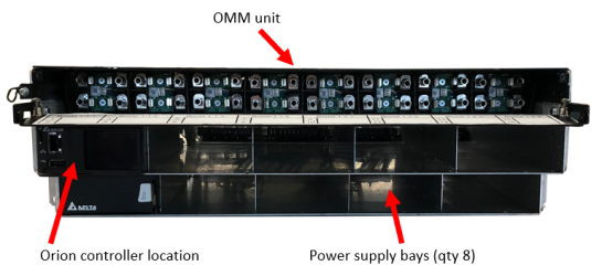
| Rack bays, modules supported | Circuit breakers 1-16 (1 output channel per breaker) Boost modules 1-8 (2 output channels per boost module) |
| Fully loaded weight (oz / lb) (see further information below) | 60.1 |
| Environmental | |
|---|---|
| Operating temperature, °C/°F | -40° to +65° / -40° to 149° |
| Relative humidity (non-condensing) | 0% to 95% |
| MTBF, hrs. | 300,000 / 40 °C | 220,000 / 55 °C |
| Approvals/compliance/certification | |
|---|---|
| UL IEC 60950, NEBS | |
| Boost module specifications | |
|---|---|
| Boost rack weight (with 1 Orion Cont., 0 brks, 0 boost bricks) (oz / lb) | 678 / 42.4 |
|
Circuit breaker weight (ea) (max qty. 16 per boost rack) (oz / lb) |
2.4 / 0.2 |
|
Boost module weight (ea) (max qty. 8ea per boost rack) (oz / lb) |
49.6 / 3.1 |
| Boost module cover weight (ea) (oz / lb) | 4.0 / 0.3 |
| Boost module maximum power added, W | 870 |
| Boost module maximum boost current per channel, A | 33 |
| Boost module maximum Voltage boost per channel, V | 29 |
| Summary of weights for reference | ||||
|---|---|---|---|---|
| # of active channels/breakers | # of boost modules | # of boost module covers | Total weight, oz | Total weight, lb |
| 0 | 0 | 0 | 678 | 42.4 |
| 1 | 1 | 7 | 758 | 47.4 |
| 2 | 1 | 7 | 761 | 47.6 |
| 3 | 2 | 6 | 809 | 50.6 |
| 4 | 2 | 6 | 811 | 50.7 |
| 5 | 3 | 5 | 859 | 53.7 |
| 6 | 3 | 5 | 862 | 53.9 |
| 7 | 4 | 4 | 910 | 56.9 |
| 8 | 4 | 4 | 912 | 57.0 |
| 9 | 5 | 3 | 960 | 60.0 |
| 10 | 5 | 3 | 962 | 60.2 |
| 11 | 6 | 2 | 1010 | 63.2 |
| 12 | 6 | 2 | 1013 | 63.3 |
| 13 | 7 | 1 | 1061 | 66.3 |
| 14 | 7 | 1 | 1063 | 66.5 |
| 15 | 8 | 0 | 1111 | 69.5 |
| 16 | 8 | 0 | 1114 | 69.6 |
| Part number | Description |
|---|---|
| PB-SYS-16-BB-01 | 19IN 16 OUTPUT DC BOOST SHELF wOMM |
| PB-PSU-162-BB | DC BOOST MODULE |
| PB-PSU-COV | SLOT BLANK COVER, PSU (for rack slots without boost module) |
| PB-BR-XX (-30, -35, -40, -50) | Circuit breaker 30A, 35A, 40A, 50A, 60A |
Important: Prior to beginning installation of hardware, a system design that evaluates the site characteristics including RRHs, installed conductors, and the DC plant must be performed. Installation (conductor sizing etc.) must comply with national and local codes.
1 −38.5 V required for startup
2 At minimum input voltage −38 V (4 feeds per system)
3 Determined by system design
4 Output must be 3 volts greater than system battery / float voltage
5 Cable gauge and radio power dependent. Must use low inductance (coaxial design) cable
6 Phoenix Contact #1745904 or equivalent
7 System design should be less than 30 amps
|
|
| ©2025 JMA Wireless. All rights reserved. All products, company names, brands, and logos are trademarks™ or registered® trademarks of their respective holders. All specifications are subject to change without notice. +1 315.431.7100 customerservice@jmawireless.com |

|

_50x50.png)