|
|

|
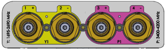
4-port 1 ft 23° panel antenna 1695-2690, 3400-4200 MHz: 2 ports 1695-2700 MHz and 2 ports 3400-4200 MHz |
|
|---|---|
|
|
| Electrical specification (min/max) | Ports 1, 2 | ||||
|---|---|---|---|---|---|
| Frequency bands, MHz | 1695-1880 | 1850-1990 | 1920-2180 | 2300-2400 | 2496-2690 |
| Polarization | ± 45° | ||||
| Average gain, dBi | 17.2 | 17.4 | 18.4 | 18.8 | 19.2 |
| Horizontal beamwidth (HBW), degrees1 | 24.5 | 23.5 | 22.3 | 21.5 | 19.0 |
| Vertical beamwidth (VBW), degrees1 | 24.5 | 23.5 | 22.3 | 21.5 | 19.0 |
| Fixed electrical downtilt (EDT), degrees | 0° | ||||
| Cross-polar isolation, port-to-port, dB1 | 25 | ||||
| Max VSWR / return loss, dB | 1.5:1 / -14.0 | ||||
| Max PIM (3rd order, 2x20W) dBc | -153 | ||||
| Maximum input power port, watts | 150 | ||||
| Electrical specification (min/max) |
|
|||
|---|---|---|---|---|
| Frequency bands, MHz | 3400-3550 | 3550-3700 | 3700-4200 | |
| Polarization | ± 45° | ± 45° | ± 45° | |
| Average gain, dBi | 18.6 | 18.8 | 19.6 | |
| Horizontal beamwidth (HBW), degrees1 | 21.5 | 20.0 | 18.5 | |
| Vertical beamwidth (VBW), degrees1 | 21.5 | 20.0 | 18.5 | |
| Fixed electrical downtilt (EDT), degrees | 0 | |||
| Cross-polar isolation, port-to-port, dB1 | 25 | 25 | 25 | |
| Max VSWR / return loss, dB | 1.5:1 / -14.0 | 1.5:1 / -14.0 | 1.5:1 / -14.0 | |
| Max PIM (3rd order, 2x20W) dBc | -145 | |||
| Maximum input power, watts | 75 | |||
| 1 Typical value over frequency. |
| Mechanical specifications | |
|---|---|
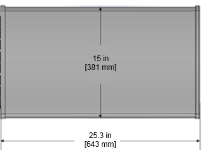
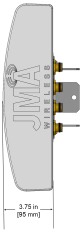
| Dimensions height/width/depth, inches (mm) |
15/ 25.3/ 3.75 (642.6/ 381/ 95.3) |
| No. of RF input ports, connector type, and location | 4 x 4.3-10 female, back |
| RF connector torque | 96 lbf·in (10.85 N·m or 8 lbf·ft) |
| Net antenna weight, lb (kg) | 12.3 (5.6) |
| Weight with supplied bracket, lb (kg) | 17.4 (7.9) |
| Shipping weight, lbs. (kg) | 23.3 (10.6) |
| Supplied bracket kit | 91900324 (included) |
| Mechanical down-tilt range | +/- 25° lateral (azimuth adjustment) and +/- 50° vertical (up/down tilt) |
| Rated wind survival speed, mph (km/h) | 120 (193) with 91900324 bracket kit |
| Frontal wind loading @ 150 km/h, lbf (N) | 16.25 (72.29) |
| Equivalent flat plate @ 100 mph and Cd=2, sq ft | 0.33 |
| Installation instructions | DX-*/SX-*/IX-* Antenna Mounting Instructions and Kits 81900511 |
| Weep hole drilling instructions | DX-*/SX-*/IX-* Antenna Weep Hole Modification Guide |
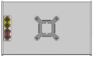
| Front view | Back view | Side view |
|---|---|---|
 |
|
 |
| Connector view | ||
|
|
||
| Array topology | Notes | |||||||||
|---|---|---|---|---|---|---|---|---|---|---|
|
Refer to JMA weep hole modification guide at jmawireless.com for mandatory drilling instructions. The SX antennas can be painted in accordance with the JMA painting guidelines at jmawireless.com |
| Ordering information | |
|---|---|
| Antenna model | Description |
| SX04FRO220-01 | 1F X-Pol 4-port panel 28°, 4.3-10 |
| 919055 | Optional inverted mounting kit for 4.0-10.0 in. OD pole |
| 91900313 | Optional bracket kit for extended horizontal and vertical tilt ranges |
V4.0
| ©2026 JMA Wireless. All rights reserved. All products, company names, brands, and logos are trademarks™ or registered® trademarks of their respective holders. All specifications are subject to change without notice. +1 315.431.7100 customerservice@jmawireless.com |