|
|

|
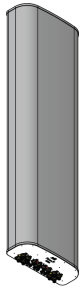
X-Pol 4-Port 6 ft, 45° Fast Roll-Off, with Smart Bias Ts, 698-894 MHz: 4 ports 698-894 MHz |
|||||||||||||||||||||||||||||||||||||||||||
|---|---|---|---|---|---|---|---|---|---|---|---|---|---|---|---|---|---|---|---|---|---|---|---|---|---|---|---|---|---|---|---|---|---|---|---|---|---|---|---|---|---|---|---|
|
|
||||||||||||||||||||||||||||||||||||||||||
|
|||||||||||||||||||||||||||||||||||||||||||

| Electrical specification (minimum/maximum) | Ports 1, 2, 3, 4 | |
|---|---|---|
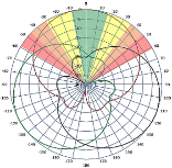
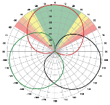
| Frequency bands, MHz | 698-806 | 806-894 |
| Polarization | ± 45° | |
| Maximum gain over all tilts, dBi | 16.0 | 16.8 |
| Average gain over all tilts, dBi | 15.8 ± 0.2 | 16.6 ± 0.2 |
| Horizontal beamwidth (HBW), degrees1 | 45 | 39 |
| Front-to-back ratio, co-polar power @180°± 30°, dB | >25.0 | >25.0 |
| Front-to-back ratio, co-polar power @180°, dB | >33.0 | >39.0 |
| X-Pol discrimination (CPR) at boresight, dB | >20.0 | >18.0 |
| Vertical beamwidth (VBW), degrees1 | 11.5 | 10.5 |
| Electrical downtilt (EDT) range, degrees | 2-12 | |
| First upper side lobe (USLS) suppression, dB1 | ≤-15.0 | ≤-15.0 |
| Cross-polar isolation, port-to-port, dB1 | 25 | 25 |
| Max VSWR / return loss, dB | 1.5:1 / -14.0 | |
| Max passive intermodulation (PIM), 2x20W carrier, dBc | -153 | |
| Max input power per any port, watts | 300 | |
| Total composite power all ports, watts | 1500 | |
1 Typical value over frequency and tilt
| Mechanical specifications | |
|---|---|
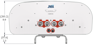
| Dimensions height/width/depth, inches (mm) | 72.0/ 20.0/ 8.0 (1828.8/ 508.0/ 203.2) |
| Shipping dimensions length/width/height, inches (mm) | 77.3/ 23.8/ 14.5 (1963.42/ 605/ 368) |
| No. of RF input ports, connector type, and location | 4 x 4.3-10 female, bottom |
| RF connector torque | 96 lbf·in (10.85 N·m or 8 lbf·ft) |
| Net antenna weight, lb (kg) | 51 (23.1) |
| Shipping weight, lb (kg) | 90 (40.8) |
| Antenna mounting and downtilt kit included with antenna | 91900318 |
| Net weight of the mounting and downtilt kit, lb (kg) | 18 (8.2) |
| Range of mechanical up/down tilt | -2° to 12° |
| Rated wind survival speed, mph (km/h) | 150 (241) |
| Frontal and lateral wind loading @ 150 km/h, lbf (N) | 129.2 (574.7), 59.8 (266.0) |
| EPA frontal and lateral, ft2, (m2) | 5.8 (0.54), 2.7 (0.25) |
| Front view | Back view | Bottom view |
|---|---|---|
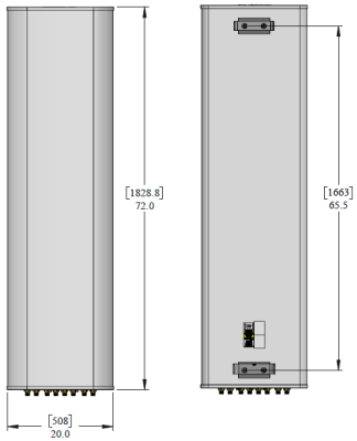
|
|
|
| Ordering information | |
|---|---|
| Antenna model | Description |
| MX04FRO645-02E | 6F X- Pol 4 PORT FRO 45⁰ 2-12⁰, 4.3-10 & SBT |
| Optional accessories | |
| AISG cables | M/F cables for AISG connections |
| PCU-1000 RET controller | Stand-alone controller for RET control and configurations |
| 91900314-02 | Dual Mount Bracket (see 91900314 bracket document for details) |
| Remote electrical tilt (RET 1000) information | |
|---|---|
| RET location | Integrated into antenna |
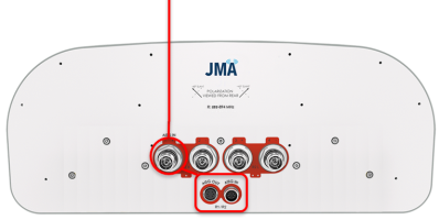
| RET interface connector type | 8-pin AISG connector per IEC 60130-9 or RF port bias-t |
| RET connector torque | Min 0.5 N·m to max 1.0 N·m (hand pressure & finger tight) |
| RET interface connector quantity | 1 pair of AISG male/female connectors and 1 RF port Bias T |
| RET interface connector location | Bottom of the antenna |
| Total no. of internal RETs 698-894 MHz | 1 |
| RET input operating voltage, vdc | 10-30 |
| RET max power consumption, idle state, W | ≤ 2.0 |
| RET max power consumption, normal operating conditions, W | ≤ 13.0 |
| RET communication protocol | AISG 2.0 / 3GPP |
| RET and RF connector topology | ||||||
|---|---|---|---|---|---|---|
| Each RET device can be controlled either via the designated external AISG connector or RF smart bias-t port as shown below: | ||||||
|
||||||
 |
||||||
| Array topology | ||||||
|---|---|---|---|---|---|---|
|
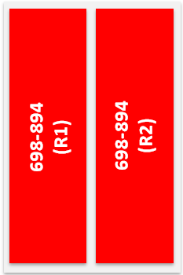
2 sets of radiating arrays R1: 698-894 MHz R2: 698-894 MHz |
|
|
||||
V4.0
| ©2026 JMA Wireless. All rights reserved. All products, company names, brands, and logos are trademarks™ or registered® trademarks of their respective holders. All specifications are subject to change without notice. +1 315.431.7100 customerservice@jmawireless.com |