|
|

|
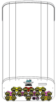
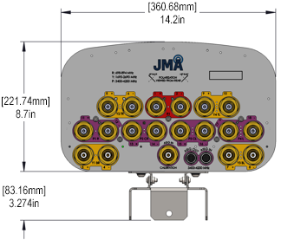
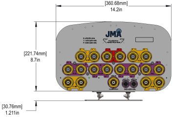
18-port panel antenna from 698-3980 MHz: 2 ports 698-894 MHz, 8 ports 1695-2690 MHz, and 8 ports 3400-3980 MHz |
|
|---|---|
|
|
| Electrical specification (min/max) | Ports 1, 2 | Ports 3, 4, 5, 6, 7, 8, 9, 10 | |||||
|---|---|---|---|---|---|---|---|
| Frequency bands, MHz | 698-798 | 824-894 | 1695-1880 | 1850-1990 | 1920-2180 | 2300-2400 | 2496-2690 |
| Polarization | ± 45° | ± 45° | |||||
| Average gain, dBi | 9.5 | 9.8 | 11.8 | 12.5 | 13.2 | 13.3 | 13.6 |
| Horizontal beamwidth (HBW), degrees1 | 72 | 70 | 68 | 66 | 64 | 62 | 60 |
| Vertical beamwidth (VBW), degrees1 | 37 | 32 | 28 | 26 | 25 | 23 | 20.8 |
| Fixed electrical downtilt (EDT), degrees | 2° | 4° | |||||
| Cross-polar isolation, port-to-port, dB1 | 25 | 25 | |||||
| Max VSWR / return loss, dB | 1.5:1 / -14.0 | 1.5:1 / -14.0 | |||||
| Max PIM (3rd order, 2x20W) dBc | -153 | -153 | |||||
| Maximum input power port, watts | 100 | 150 | |||||
| 1 Typical value over frequency. |
| Electrical specification (minimum/maximum) | Ports 11, 12, 13, 14, 15, 16, 17, 18 |
|---|---|
| Frequency bands, MHz | 3400-3980 |
| Gain, dBi | 16.7 |
| Horizontal beamwidth (HBW), degrees | 75 |
| Horizontal beamwidth tolerance, degrees | ±5 |
| Front-to-back ratio, co-polar power @180°± 30°, dB | 27 |
| Vertical beamwidth (VBW), degrees1 | 6.8 |
| Vertical beamwidth tolerance, degrees | ±0.3 |
| Electrical downtilt (EDT), degrees | 2-12 |
| First upper side lobe (USLS) suppression, dB1 | 17 |
| Coupling level, Amp, Antenna port to Cal port, dB | 26 |
| Coupling level, max Amp Δ, Antenna port to Cal port, dB | ±0.7 |
| Coupler, max Amp Δ, Antenna port to Cal port, dB | 0.65 |
| Coupler, max Phase Δ, Antenna port to Cal port, degrees | 5 |
| Cross-polar isolation, port-to-port, dB1 | 22 |
| Isolation, Inter-band, dB | 20 |
| Max VSWR / return loss, dB | 1.5:1 / -14.0 |
| Max passive intermodulation (PIM), 2x20W carrier, dBc | -145 |
| Max input power per port at 50 °C, watts | 75 |
| Electrical specification, Broadcast 65° | Ports 11, 12, 13, 14, 15, 16, 17, 18 |
|---|---|
| Frequency bands, MHz | 3400-3980 |
| Gain over all tilts, dBi | 21.6 |
| Horizontal beamwidth (HBW), degrees1 | 65 |
| Horizontal beamwidth tolerance, degrees | ±4 |
| Vertical beamwidth (VBW), degrees1 | 6.8 |
| Vertical beamwidth tolerance, degrees | ±0.3 |
| First upper side lobe (USLS) suppression, dB1 | <-16 |
| Electrical specification, Service Beam | Ports 11, 12, 13, 14, 15, 16, 17, 18 |
|---|---|
| Frequency bands, MHz | 3400-3980 |
| Steered 0° gain, dBi | 21.6 |
| Steered 0° Gain tolerance, dBi | ±0.6 |
| Steered 0° Beamwidth, Horizontal, degrees | 22 |
| Steered 0° CPR at beampeak, dB | 18 |
| Steered 0° Horizontal Sidelobe, dB | 12 |
| Steered 30° Gain, dBi (max) | 21.2 |
| Steered 30° Gain tolerance, dBi | ±0.6 |
| Steered 30° Gain, dBi | 21 |
| Steered 30° Beamwidth, Horizontal, degree | 22 |
| Steered 30° CPR at beampeak, dB | 18 |
| Steered 30° Horizontal Sidelobe, dB | 10 |
| Ordering information | |
|---|---|
| Antenna model | Description |
| DX18FRO265-01 | 2F panel antenna, 18 ports, (2) 698-894, (8) 1695-2690 four degrees EDT, (8) 3400-3980 with 2-12° RET, 4.3-10 & SBT |
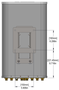
| Mounting kit (included) | Fixed-mount and 91900324 articulating brackets with X- and Y-axis adjustments and rotation |
| Mechanical specifications | |
|---|---|
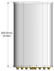
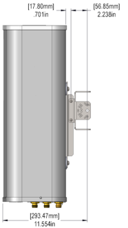
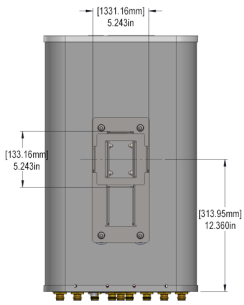
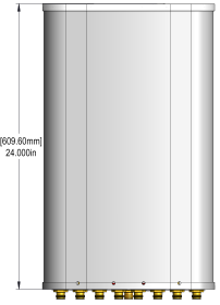
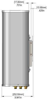
| Dimensions height/width/depth, inches (mm) | 24/ 14.2/ 8.5 (609.6/ 360.7/ 215.9) |
| No. of RF input ports, connector type, and location | 18 x 4.3-10 female, bottom & 1 cal x 4.3-10 female, bottom |
| RF connector torque | 96 lbf·in (10.85 N·m or 8 lbf·ft) |
| Net antenna weight, lb (kg) | 21.2 (9.6) |
| Weight with supplied pipe mount bracket, lb (kg) | 26.2 (11.9) |
| Shipping weight, lb (kg) | 41.9 (19.0) |
| Rated wind survival speed, mph (km/h) | 150 (241) |
| Frontal wind loading @ 150 km/h, lbf (N) | 22.3 (99.4) |
| Installation instructions | See instructions 81900530-01. |
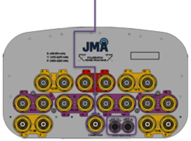
| Front view pole-mount | Side view pole-mount | Back view pole-mount |
|---|---|---|
 |
|
|
| Bottom view pole-mount |
|---|
|
|
| Front view fixed-mount | Side view fixed-mount | Back view fixed-mount |
|---|---|---|
 |
|
|
| Bottom view fixed-mount |
|---|
|
|
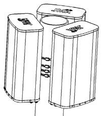
| Top view tri-sector pole-mount | Side view tri-sector pole-mount |
|---|---|
 |
|
| Remote electrical tilt (RET 1000) information | |
|---|---|
| RET location | Integrated into antenna |
| RET interface connector type | 8-pin AISG connector per IEC 60130-9 or RF port bias-t |
| RET connector torque | Min 0.5 N·m to max 1.0 N·m (hand pressure & finger tight) |
| RET interface connector quantity | 1 pair of AISG male/female connectors and 1 RF port bias-t |
| RET interface connector location | Bottom of the antenna |
| Total no. of internal RETs 3400-3980 MHz | 1 |
| RET input operating voltage, vdc | 10-30 |
| RET max power consumption, idle state, W | ≤ 2.0 |
| RET max power consumption, normal operating conditions, W | ≤ 13.0 |
| RET communication protocol | AISG 2.0 / 3GPP |
| RET and RF connector topology | ||||||
|---|---|---|---|---|---|---|
| Each RET device can be controlled either via the designated external AISG connector or RF port as shown below: | ||||||
|
|
||||||
|
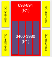
| Array topology | ||||||||||
|---|---|---|---|---|---|---|---|---|---|---|
|
6 sets of radiating arrays
R1: 698-894 MHz Y1: 1695-2690 MHz Y2: 1695-2690 MHz Y3: 1695-2690 MHz Y4: 1695-2690 MHz |
|
|
||||||||
V3.0
| ©2026 JMA Wireless. All rights reserved. All products, company names, brands, and logos are trademarks™ or registered® trademarks of their respective holders. All specifications are subject to change without notice. +1 315.431.7100 customerservice@jmawireless.com |