|
|

|
12-port cylinder antenna 1695-4200 MHz: 4 ports 1695-2690 MHz and 8 ports 3700-4200 MHz |
|
|---|---|
|
|


| Electrical specification (min/max) | Ports 1, 2, 3, 4 | |||
|---|---|---|---|---|
| Frequency bands, MHz | 1695-1880 | 1850-1990 | 1920-2280 | 2300-2690 |
| Polarization | ± 45° | |||
| Gain, dBi (max) | 9.4 | 9.6 | 10.0 | 10.5 |
| Gain, dBi (average) | 9.0±0.4 | 9.2±0.4 | 9.5±0.5 | 10.0±0.4 |
| Horizontal beamwidth (HBW), degrees1 | 360° | |||
| Vertical beamwidth (VBW), degrees1 | 15.2 | 14.0 | 13.2 | 10.7 |
| Cross-polar discrimination over 360°1 | 16.0 | 17.0 | 17.5 | 18.0 |
| Electrical downtilt (EDT), degrees | 2° or 4° or 6° or 8° | |||
| Cross-polar isolation, dB1 | 25 | |||
| Max VSWR / return loss, dB | 1.5:1 / -14.0 | |||
| Max PIM, 3rd order 2x20W carrier, dBc | -153 | |||
| Maximum input power port, watts | 125 | |||
| 1 Typical value over frequency and tilt. |
| Electrical specification, single column (non-beamforming) (minimum/maximum) | Ports 5, 6, 7, 8, 9, 10, 11, 12 |
|---|---|
| Frequency bands, MHz | 3700-4200 |
| Gain, dBi | 9.8 |
| Vertical beamwidth (VBW), degrees1 | 9.4 |
| Vertical beamwidth tolerance, degrees | ±0.5 |
| Tilt, degrees | 2 |
| First upper side lobe (USLS) suppression, dB1 | 15 |
| Coupling level, Amp, Antenna port to Cal port, dB | 26 |
| Coupling level, max Amp Δ, Antenna port to Cal port, dB | ±0.4 |
| Coupler, max Amp Δ, Antenna port to Cal port, dB | 0.5 |
| Coupler, max Phase Δ, Antenna port to Cal port, degrees | 4 |
| Cross-polar isolation, port-to-port, dB1 | 25 |
| Max VSWR / return loss, dB | 1.5:1 / -14.0 |
| Max passive intermodulation (PIM), 2x20W carrier, dBc | -145 |
| Max input power per port at 50 °C, watts | 75 |
| Electrical specification, Broadcast 65° | Ports 5, 6, 7, 8, 9, 10, 11, 12 |
|---|---|
| Frequency bands, MHz | 3700-4200 |
| Gain over all tilts, dBi | 14.4 |
| Horizontal beamwidth (HBW), degrees per sector1 | 80 |
| Vertical beamwidth (VBW), degrees1 | 9.4 |
| Vertical beamwidth tolerance, degrees | ±0.5 |
| First upper side lobe (USLS) suppression, dB1 | <-15 |
| Electrical specification, Service Beam | Ports 5, 6, 7, 8, 9, 10, 11, 12 |
|---|---|
| Frequency bands, MHz | 3700-4200 |
| Steered 0° gain, dBi | 14.4 |
| Steered 0° Gain tolerance, dBi | ±0.6 |
| Steered 0° Beamwidth, Horizontal, degrees | 22 |
| Steered 0° CPR at beampeak, dB | 18 |
| Steered 0° Horizontal Sidelobe, dB | 14 |
| Steered 30° Gain, dBi (max) | 13.6 |
| Steered 30° Gain tolerance, dBi | ±0.6 |
| Steered 30° Beamwidth, Horizontal, degree | 26 |
| Steered 30° CPR at beampeak, dB | 18 |
| Steered 30° Horizontal Sidelobe, dB | 10 |
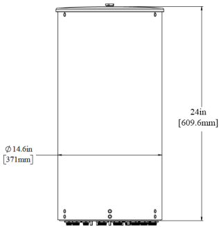
| Mechanical specifications | |
|---|---|
| Dimensions height/diameter, inches (mm) |
24.0/ 14.6 (609.6/ 370.8) |
| Antenna volume (cubic feet) | 2.32 |
| No. of RF input ports, connector type, and location | 12 x 4.3-10 female, bottom |
| Calibration interface port, connector type, and location | 1 x 4.3-10 female, bottom |
| RF connector torque | 96 lbf·in (10.85 N·m or 8 lbf·ft) |
| Net antenna weight, lb (kg) | 30 (13.6) |
| Rated wind survival speed, mph (km/h) | 150 (241) |
| Frontal wind loading @ 160 km/h, lbf (N) | 47.6 (211) |
| Front view | End view |
|---|---|
 |
The 0 degree reference arrow corresponds to the 0 degree position in the antenna pattern file. Each antenna pattern file uses a top down orientation view (the patterns are viewed from the top of the antenna looking down). |
|
|
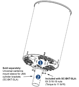
| End view details: 6 stud bolts for direct mount to the Universal Sleeve (SC-BKT-SLA) |
| Ordering information | |
|---|---|
| Antenna model | Description |
| CX12OMI236-BFx (x represents the fixed down tilt value per 4 ports for 1695-2690 MHz |
2ft 12 Port OMNI antenna 4MB 8LS6 |
| x= 2, 4, 6, or 8 deg per 4 ports 1695-2690 MHz x= FET value for ports 1, 2, 3, 4 (Y1, Y2) |
|
| Notes on mounting brackets | Example bracket configuration |
|---|---|
|
|
| Small Cell solutions and mounting systems (sold separately) | |||
|---|---|---|---|
| Side Arm Mounting System | SC-BKT-SA-(color) | Wide Diameter Pole | SC-BKT-WTPE-(color) |
| Steel Pole Mounting System | SC-BKT-SLA (color) | ||
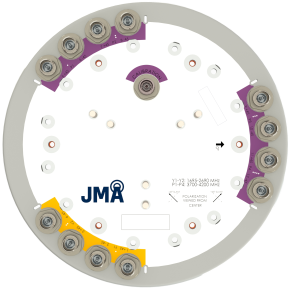
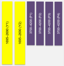
| Array topology | ||
|---|---|---|
|
6 sets of radiating arrays Y1: 1695-2690 MHz Y2: 1695-2690 MHz P1: 3700-4200 MHz P2: 3700-4200 MHz P3: 3700-4200 MHz P4: 3700-4200 MHz |
 |
|
V2.0
| ©2026 JMA Wireless. All rights reserved. All products, company names, brands, and logos are trademarks™ or registered® trademarks of their respective holders. All specifications are subject to change without notice. +1 315.431.7100 customerservice@jmawireless.com |